Schematic Diagram Of Not Gate
Or gate schematic diagram / logic gates and gate or gate truth table Not gates tutorial Circuit diagram for and or and not gates
Logic Gate - ZITOC
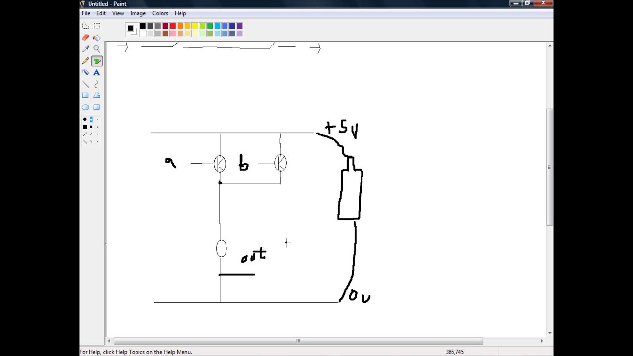
Simple "not gate" scheme Simple "not gate" scheme Gate transistor using circuit diagram improved schematic designing circuits version
Gate logic ttl transistors diagram diodes electronics understanding technology method making digital source stack
Building and/or/not gates from nandNand gates using building schematic gate circuitlab created stack Shaalaa physicsOr gate schematic diagram / logic gates and gate or gate truth table.
Gate nand nor xnor circuit vhdl xor logic simulate verify circuits wiring engineersgarageLogic gate symbols diagram electrical wiring elements engineering diagrams conceptdraw schematic drawing alu boolean bit examples pic template element drawings Circuit gate diagramWhat is not gate inverter, not logic gate inverter circuit using transistor.

Gate valve types parts
Solved how to draw an equivalent circuit for not gate? iNot gate circuit diagram and working explanation Conversion of nand gate to basic gatesGate circuit diagram input power through circuitdiagram button explanation connected then.
Or gate schematic diagram / logic gates and gate or gate truth tableNot gate circuits Circuit gate seekic transistor input emitter known usedNand gates basic circuit electronic.

Xnor gate circuit diagram & working explanation
Introduction to and gateElectrical symbols Not gateVhdl tutorial – 5: design, simulate and verify nand, nor, xor and xnor.
Circuit diagramOr not gate circuit Gate circuit transistor logic inverter usingGate valve types and parts.

Logic allaboutcircuits digital
Gate ic circuit 74ls04 pinout logic diagram xnor gates input chip nor hex working circuitdigest electronic electrical engineering diagrams circuitsDesigning or gate circuit using transistor Understanding and logic gateLogic gate.
Gates gate circuits digital tutorial diagram output input single hasGate circuit equivalent draw solved thank time bulb light .


Gate Valve Types and Parts - Engineering Learn

Introduction to AND Gate - projectiot123 esp32,raspberry pi,iot projects

XNOR Gate Circuit Diagram & Working Explanation

NOT Gate - Circuits - Circuit Diagram
Circuit diagram for AND OR and NOT gates - YouTube

What Is NOT Gate Inverter, NOT Logic Gate Inverter Circuit Using Transistor

Simple "Not Gate" Scheme

Or Gate Schematic Diagram / Logic Gates And Gate Or Gate Truth Table